
Quiet manoeuvring and cruising
The motors drive the shaft from the battery. The diesel stays off. The helm lever controls speed directly, with smooth ramps in both directions.
H1G Drive adds two electric motors to each propeller shaft, next to the existing diesel. Leave harbour and arrive with no noise or exhaust. When the diesel runs, the same motors become generators and refill the battery.
Project report, 23 October 2026. It was compiled from the project's source code, the motor-controller firmware and the test logs recorded on the development installation. Every number is marked as Rated, Measured, Derived or Not yet measured. Only measured numbers belong on a spec sheet.
Recorded on 6 October 2026 at the development installation: the motors on their test frame, and the helm software running live on a Simrad NSS evo3S chart plotter. Tap a moment on the right to jump to it.
The video is not included in this copy. Watch it at vps.greenlinedrive.com.
Recorded on 15 October 2026 on the boat at 7.8 knots, on electric drive only with the diesels off. Turn the sound on: what you hear is the wake and the water, not the drive. Tap a moment to jump to it.
The video is not included in this copy. Watch it at vps.greenlinedrive.com.
The motors sit on the propeller shafts alongside the diesel engines, which makes this a parallel hybrid. A modular LFP battery, one master pack plus slave packs, feeds a common DC bus. A supervisory computer links every device over CAN and drives the display on the boat's chart plotter.
The motors drive the shaft from the battery. The diesel stays off. The helm lever controls speed directly, with smooth ramps in both directions.
The diesel drives the boat. The motors switch to generator mode automatically once the shaft has turned steadily for 2 seconds, and charge the battery with up to 400 Nm per shaft.
Port can run electric while starboard charges under diesel. Every shaft decides its own mode, and the helm shows both at a glance.
Four motor-inverters, two per shaft, 25 kW each. 50 kW per shaft, continuous and peak. Peak torque (400 Nm per shaft) for 60 seconds to accelerate, then automatic fallback to 320 Nm continuous.
Modular LFP packs, 57.6 V and 18.1 kWh each: one master plus slaves in parallel, built and certified by TAB Mežica. REC 10M battery management running our own application, adapted to this hybrid drive.
Runs on the boat's existing Simrad chart plotter. A supervisory computer logs every value and syncs to shore for remote monitoring and alarms.
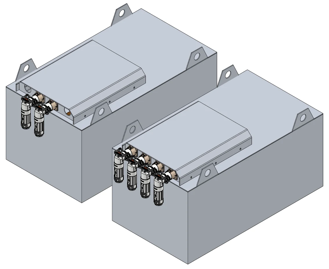
The battery is modular. One master pack is always fitted, and slave packs are added in parallel to reach the energy the boat needs. Every pack is a sealed unit with its own cells, battery management, precharge, contactors, fuse and current measurement. Packs are built and certified by TAB Mežica. The test installation has been ordered with one master and four slave packs.
Each shaft carries one Boeli DDHPS300 SPS30 permanent-magnet synchronous motor, built from two independent 25 kW units on the same shaft. Each unit has its own EMSISO inverter, so a shaft has a master and a slave drive that share the load. The motor sits in the shaft line through a bellhousing, next to the diesel.
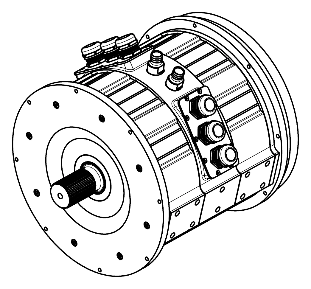
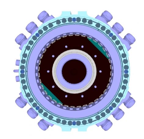
The housing wall around the stator carries a ring of axial channels, evenly spaced over the full circumference. Water-glycol flows through all of them, so the coolant surrounds the stator on every side and takes heat straight from the windings and the iron.
Because there is no cold side and no hot side, the stator stays at an even temperature. This is what lets each unit deliver 160 Nm continuously (rated at 100 °C), inside a closed housing in the engine room.
The motors sit on the boat's internal coolant loop. The PDM starts the pumps at key-on, and a heat exchanger passes the heat to sea water.
Node numbers are the CANopen IDs the shared Lua script uses to tell the four controllers apart at runtime. On the test installation, the two shafts are mechanically coupled, so one shaft can drive the other. That is why the logs show combinations such as "port electric while starboard generates".
| Component | Source | Our contribution |
|---|---|---|
| Motors ×2 | Boeli DDHPS300 SPS30 · 2 × 25 kW stator sets each | Specification for this drive |
| Inverters ×4 | EMSISO (supplier) · 25 kW each | Control script, 1,150 lines of Lua: state machine, generator torque law, derating, protections |
| Supervisory server | Own | 6,086 lines of Python: CAN decoding, WebSocket server, logging, alarms, cloud sync, bench tools |
| Helm dashboard | Own | 15 canvas modules for the Simrad NSS evo3S: main, battery, cells, engines, history, CAN diagnostics, calibration |
| Battery pack | TAB Mežica (assembly and certification) | Specification for this drive |
| BMS | REC 10M (hardware) | Our own BMS application, adapted to this hybrid drive; per-cell monitoring and parameter console on the helm |
| Inverter/charger, solar | Victron (supplier) | Read over NMEA 2000, mode control |
| Power distribution | PDM (supplier) | Read and displayed |
| Display | Simrad NSS evo3S (supplier) | Hosts our HTML5 app |
| Fleet back end and mobile app | Own (in progress) | Remote sync, push alarms, AI troubleshooting chat |
Total own code in the boat repository: about 17,800 lines. This table shows what was written. Who legally owns it is a separate question, answered in chapter 10.
Power is limited to 50 kW per shaft (25 kW per inverter), both continuous and peak. Below that, torque is the limit. Peak torque is allowed for 60 seconds to accelerate, then the drive falls back to continuous torque by itself.
Curves: Rated values. Dots: Measured shaft power (torque × speed) per shaft, 15-second steady samples from the 1 and 5 October tests (249 samples, 162–840 rpm). The rating itself has not yet been confirmed by a thermal endurance run.
This is the real helm software that runs on the boat's chart plotter. Here it is fed by a scripted voyage instead of the CAN bus, so you can try it without the boat. Message formats and value ranges are copied from a live recording on 6 October 2026.
The same boat in the owner's pocket. The app reads the boat over the fleet server from anywhere with a connection. Here it runs on the same simulated voyage as the helm screen above.
Choose a voyage profile and adjust the assumptions. The model uses the firmware's real limits (generator torque law, voltage derating, 2,400 rpm cap) on top of a simple propeller load curve. Play the voyage to watch the instruments.
Sign convention, the same as on the helm: negative means the shaft draws from the battery (electric drive) and positive means it charges (generator). The model limits each shaft to its 50 kW rating and generator torque to the 320 Nm continuous rating.
All four inverters run the same control script. It reads the throttle and the battery over CAN, decides the operating state and protects the battery, the motors and the diesel. The values below are the settings in the current firmware file, so they describe the design, not test results.
Generator mode starts only after the shaft has stayed above 110 rpm with the lever in neutral for 2 continuous seconds. That means the diesel is turning the shaft. This dwell was added on 10 Sep 2026 after electric coast-down was mistaken for a running diesel.
Torque ramps in from 60 to 80 rpm, then stays at nominal up to 2,420 rpm. Above 2,480 rpm the diesel-overspeed shutdown trips. Torque changes are rate-limited to 100 Nm/s, and a return to neutral ramps speed down at 200 rpm/s.
Each result below states how it was obtained. Rated numbers are the design ratings of the drive. Measured numbers come from instrument readings on the development installation. Derived numbers are calculated from measurements. Items not yet measured have no number and stay off the spec sheet.
On the test rig both shafts are coupled, so one shaft can drive the other. The driving shaft turns battery power into shaft power and the other shaft turns it back into electricity. Efficiency follows from the inverter DC power and the shaft power (torque × speed) on each side. The torque readings pass a cross-check: both sides of the same shaft agree within 1.5 %, and the difference is friction.
| Window | Speed | Torque / shaft | Drive: DC in → shaft | Eff. drive | Generator: shaft → DC out | Eff. gen |
|---|---|---|---|---|---|---|
| 5 Oct · 11:31–11:35 | 836 rpm | 324 Nm | 36.2 → 28.3 kW | 78 % | 27.9 → 21.1 kW | 76 % |
| 5 Oct · 11:26–11:28 | 729 rpm | 333 Nm | 33.7 → 25.5 kW | 76 % | 25.1 → 18.0 kW | 72 % |
| 5 Oct · 11:16–11:20 | 480 rpm | 342 Nm | 25.4 → 17.2 kW | 68 % | 17.1 → 9.9 kW | 58 % |
| 1 Oct · 10:51–10:55 | 456 rpm | 46–150 Nm | 2.6 → 2.2 … 9.1 → 7.2 kW | 76–86 % | — | — |
| 5 Oct · 13:13–13:14 | 297 rpm | 399 Nm | 22.5 → 12.4 kW | 55 % | 12.4 → 2.6 kW | 21 % |
Losses stay at about 8 kW per shaft at 320–340 Nm whatever the speed, and grow with torque. That is the signature of copper (I²R) losses. Shaft power rises with speed while these losses do not, so efficiency rises with speed at the same torque. A two-term loss model fitted to 142 steady drive samples from 1 and 5 October (error ±0.26 kW, 34–399 Nm, 162–840 rpm) gives:
Loss per shaft ≈ 6.81·10⁻⁵ × T² + 0.88·10⁻³ × rpm (kW, T in Nm). Measured range 162–840 rpm at 34–399 Nm. Beyond 840 rpm the curve is Derived: about 86 % at the rated point (320 Nm, 1,492 rpm, 50 kW). Iron losses grow faster than linearly at high speed, so the model may be optimistic there. A dyno run should confirm it.
These are the known problems, with the evidence for each and the next step. Each one would stop a customer installation as things stand.
| Severity | Issue | Evidence | Next step |
|---|---|---|---|
| High | Speed runaway during hard acceleration With high generator torque on the other shaft, shaft speed runs away to the 2,400 rpm cap and trips the overspeed protection. | Reproduced twice (10 Sep) at about 17 kW combined. Three software changes did not fix it. Lowering the other shaft's generator torque brings speed back. Steady operation is unaffected (36 kW drive held for 5 minutes on 5 Oct). | Raise it with EMSISO as a control-loop question. It is likely specific to the coupled test rig, where speed control on one shaft fights torque control on the other. |
| High | Supervisor CAN drop-out while the power stage is on | Since wiring work on 6 Oct, the supervisor receives and sends nothing for as long as the motors are energised. The inverters then trip on throttle timeout after 250 ms. Electric drive worked until 5 Oct. | Hardware: check CAN ground reference, transceiver isolation, termination and shielding. |
| Medium | Inverter and battery readings differ by ~1.9 kW | On 5 Oct (11:31–11:35) the inverters' net DC power was 15.1 kW and the BMS showed 10.6 kW. The shore charger supplied 2.6 kW of that gap (Victron, 2.9 kW AC in), leaving about 1.9 kW. On 10 Sep a similar 1.7 kW gap was seen. Both ends matched a clamp meter at low current. | Clamp-meter check at high current with shore power off, then trace every path on the DC bus. |
| Medium | Generator power reads above the physical limit | In 70 of 189 generator samples, the reported DC power exceeds what 400 Nm can produce at the logged speed. | Check against the BMS current and a clamp meter at high generator power. Ask EMSISO how DC power is computed in generator mode. |
| Low | September torque data not usable | It implied 117 % / 138 % efficiency. The October data is consistent, so the issue looks fixed in the meantime. | Confirm with a torque sensor during the dyno run. |
| Low | Small jerk at the end of a ramp-down | Velocity control on one shaft fights torque control on the other on the coupled rig. | Retest on separate shafts in the real boat. |
| Low | Cross-shaft power coordinator | Written, running in log-only (dry-run) mode. | Review the logs, then enable. |
These are the six questions from the business-plan request. Each one shows what the project record can already answer and what still needs a decision or input from the founders.
Enter the bill of materials and labour at one reference volume. The model applies a learning curve to estimate cost at 50, 250 and 1,000 units a year, then compares the result with the price of a 10 kW electric kit plus a generator.
| Units / year | Cost price | Selling price | vs 10 kW kit + generator |
|---|
Learning curve: cost × (rate)log₂(volume / 50), applied to both hardware and labour. Selling price = cost ÷ (1 − margin). The model holds no project figures until they are entered.
These steps turn the "not yet measured" items into measured numbers, in order of dependency.